Garage Compressed Air System Piping Diagram
Garage compressed air system piping diagram. There are a variety of applications that can be performed with a garage-based compressed air system. The only reason I didnt was to keep costs down. Reduce the moisture within your air compressor piping diagrams by changing the supply inlet.
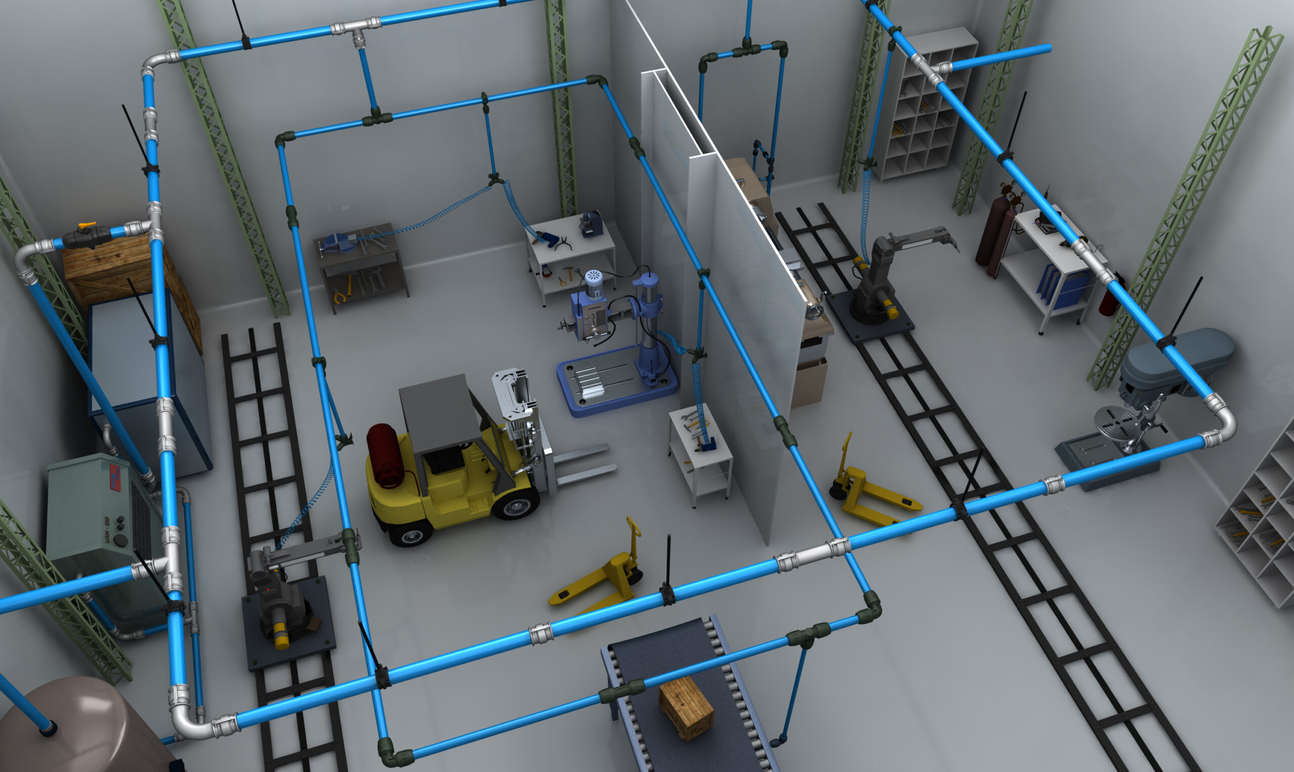
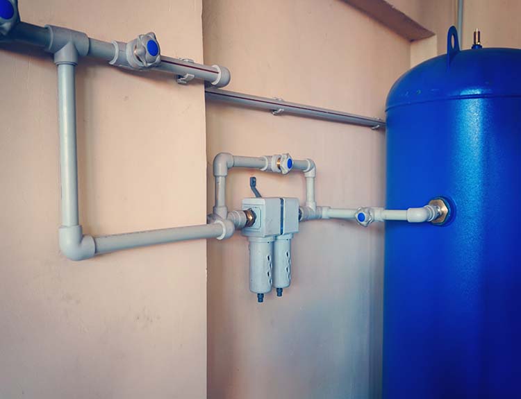
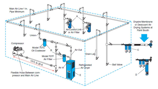
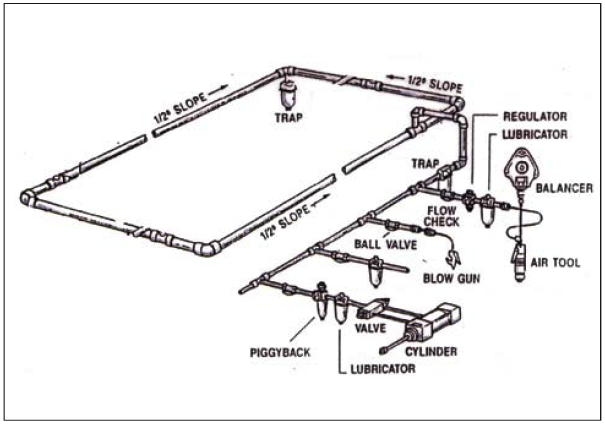
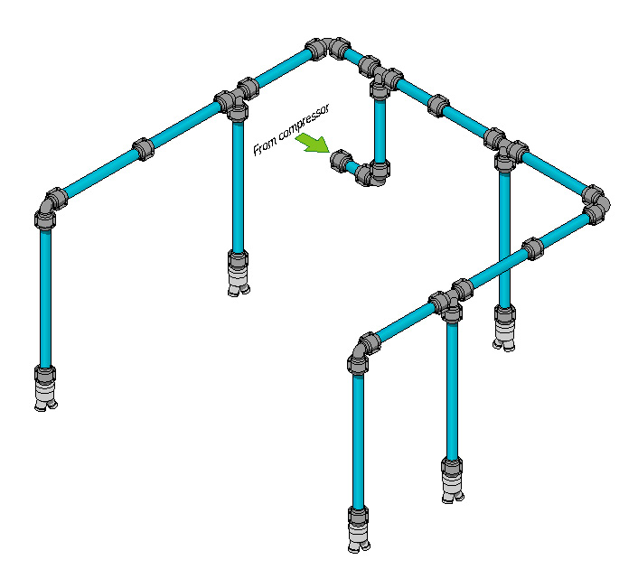
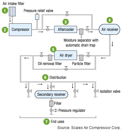
It is important to plan for future maintenance and be ahead of yourself when planning your air compressor piping diagram. A bypass pipe should be put in place to continue the transportation of compressed air when maintenance needs to be completed. From cutting and sawing to nailing and riveting.
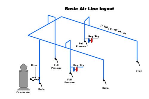
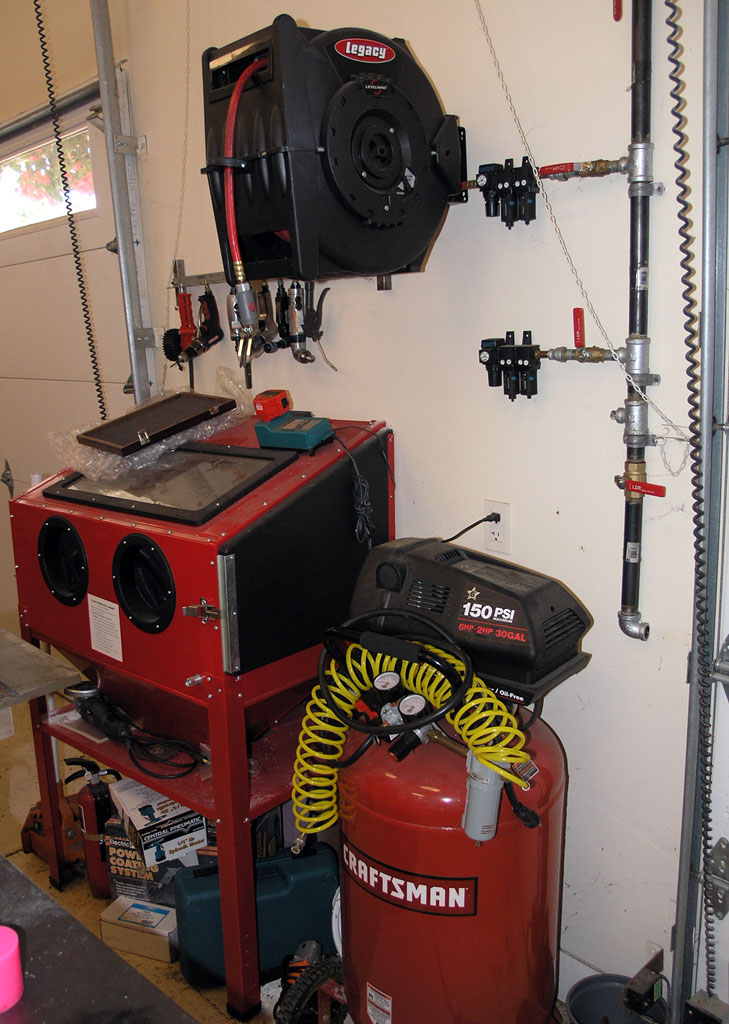
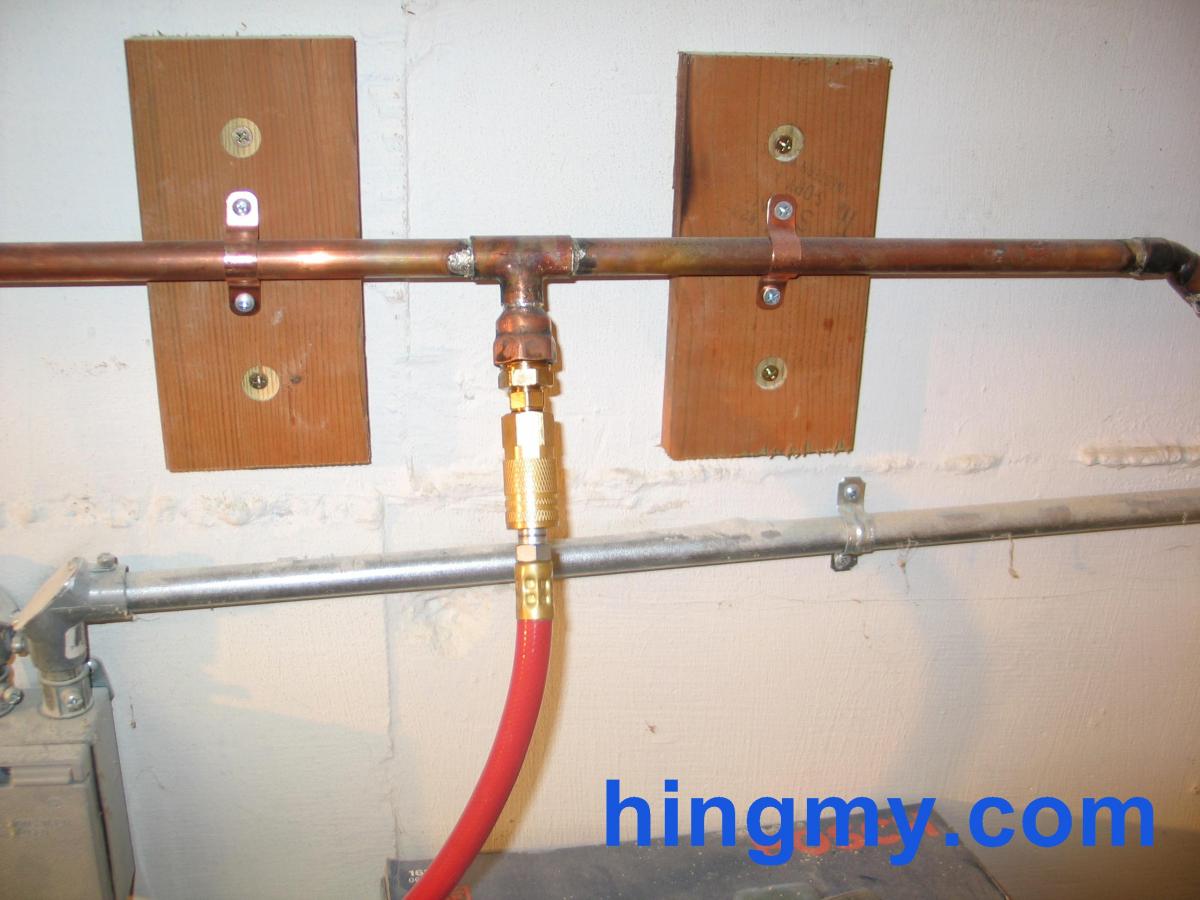
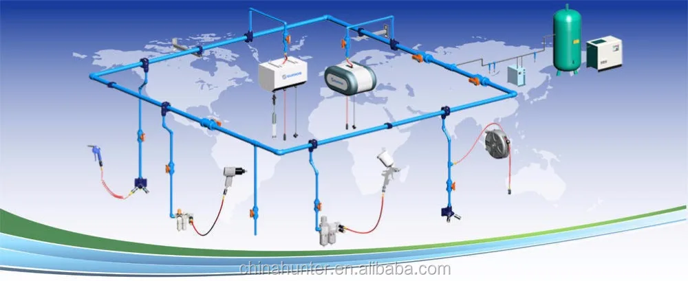
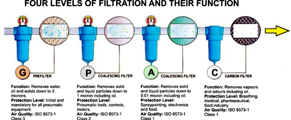
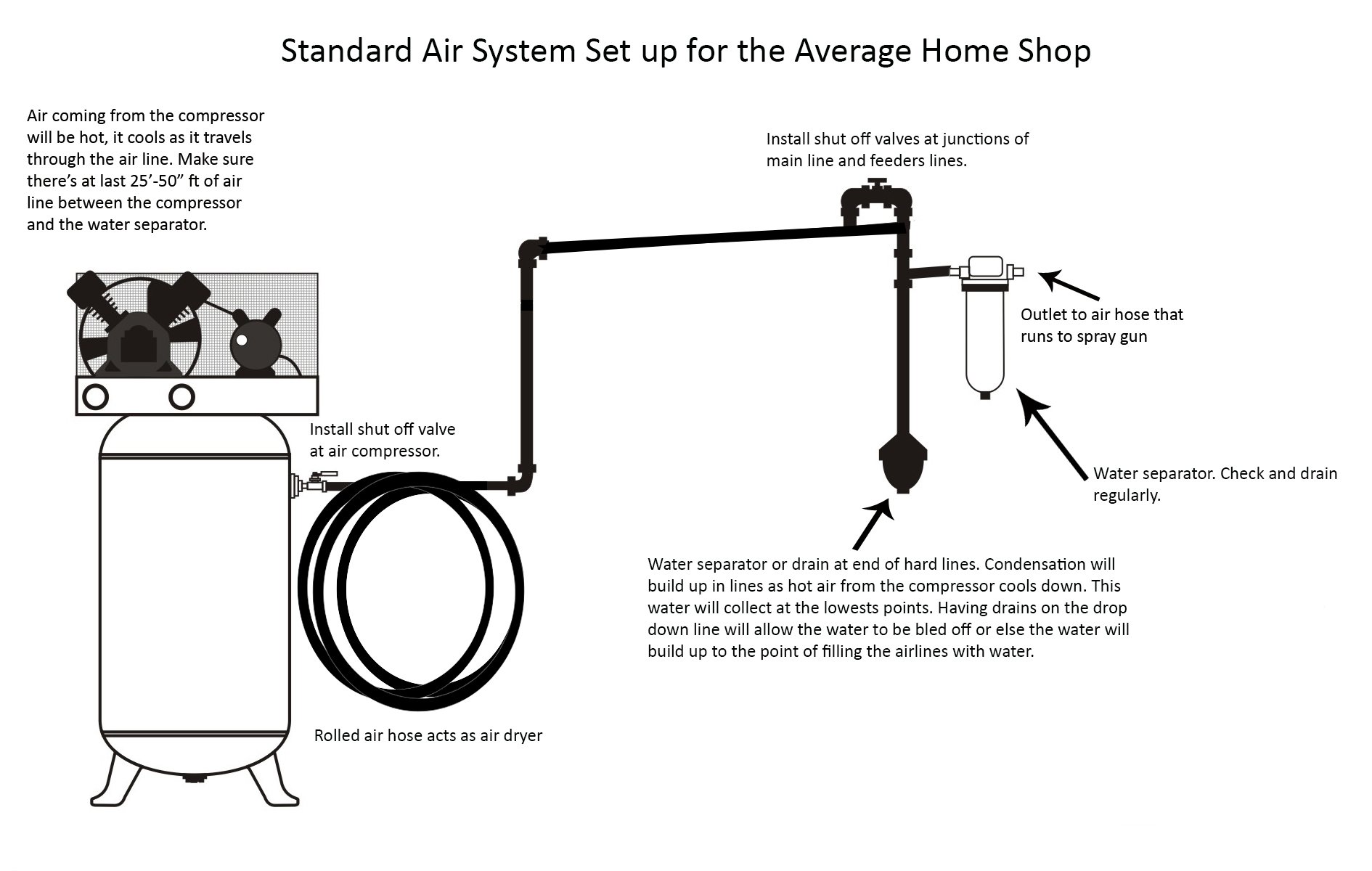
My piping run is about 25 feet and I use 12 diameter copper pipe however I could have used 34 diameter pipe as well. The RapidAir garage air line kit allows you to design and install your own pressurized air system any way you want it. Here you have your air compressor plugged into the mains preferably by your garage door that will be connected to your piping with a flexible hose attached straight to a filter before entering the piping system the air can then pass through a regulator before entering the air hose reel and into the tool for your application.
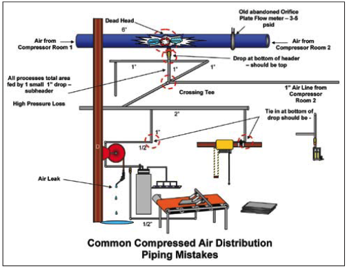
If you want a quiet yet powerful air compressor for your garage then go for the Makita MAC2400. The following three plastic materials however are all suitable choices for piping compressed air. Taking air from the top of a compressor means that the amount of moisture taken with it too is reduced.
From this point I soldered together34 copper pipe from this location up to the woodworking shop and also a branch for the garage. If there is any doubt that a pipe size may create a pressure drop use the next largest size. I personally use a very minimal amount of pipe for my compressed air system.
Acrylonitrile butadiene styrene ABS. Design Your Own Compressed Air Piping System. Installing Compressed Air Piping System from your Piping Diagrams Sketch - YouTube.
Once you get your system up and running and turn it on you might hear some air leaking out. You wont find an easier to install system than RapidAir.
This helps because water is heavier than air and drops to the bottom of the tank.
When youve completed the design save your project by creating an account. My piping run is about 25 feet and I use 12 diameter copper pipe however I could have used 34 diameter pipe as well. Instead it will be squeezing it down into the threads. Draw a piping schematic and show all. The quality of our compressed air is also effected by how our air delivery lines are laid out in our shops. Acrylonitrile butadiene styrene ABS. For all the piping in the compressor. This kind of piping is produced specifically for compressed air systems. Attach AIRnet copper or galvanized piping to the outlet that points toward the compressor.
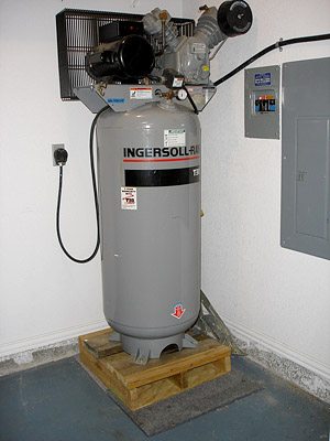
Compressed Air System Piping Diagram. I have a two-car garage with a 60 gallon air compressor outputting about 12cfm 90psi. Reduce the moisture within your air compressor piping diagrams by changing the supply inlet. You can find ABS in a variety of products from car fenders to LEGO-brand toy bricks. Image Result For Shop Air Compressor Piping Diagram Air. I created a simple vertical drop of pipe below the first riser with a valve on it. Our drag-and-drop features give you complete control over your design.


















Post a Comment for "Garage Compressed Air System Piping Diagram"